The Open Systems Interconnection (OSI) model is a generic reference to understanding how computers communicate with each other. It’s not meant to be an exact science, but rather a guide to help us visualize what happens during node-to-node communication. I once made a post on the OSI model before, but it was lacking detail. There is another conceptual model that we use, called the TCP/IP model. It’s a better model and is preferable to solving network issues. But, before I discuss this model, I’ll do a recap on the OSI model.
The OSI Model

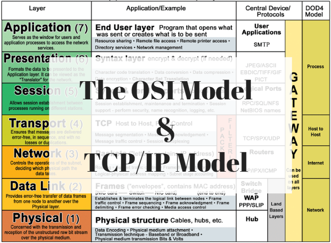
The OSI model includes 7 layers. This model is definitely great for beginners, but it’s not all that best for modern communication. For now, just pay attention to the left-hand column. The information in the remaining columns will become clearer as I go through each layer. You can see the TCP/IP model (also called the DOD4 model) on the last column on the right.
The Application Layer
At the top of the OSI reference model sits layer 7, also called the “Application layer.” At this layer lies the interface of the applications we use every day. It is what we see on our screen. The applications we use, such as our Web browsers, don’t actually reside in the Application layer itself; however, they do interface with Application layer protocols, such as HTTP and other popular protocols, like Telnet, FTP, SNMP, HTTPS, DNS, DHCP, and so forth. There are a vast array of protocols working together at this layer.
These protocols are used to transmit information from a sending machine to a receiving machine. Using the same example as above, HTTP is a protocol used on the World Wide Web (WWW). It’s the Application layer protocol that defines the communication between a web browser and a web server. It specifically run on TCP port 80 by default and it’s how Internet users request HTML-formatted files.
The Presentation Layer
If you’ve ever seen a raw web page, you’ll understand that they are composed of HTML, JavaScript, ASCII/Unicode, image files, and audio files. These are things that the average Internet user cannot read. But, the Presentation layer converts this machine-readable code into something Internet users can easily read and “presents” it to the Application layer.

Because of this function, the Presentation layer is often referred to as the “translator” of the OSI reference model. The Presentation layer is also typically where encryption and decryption takes place, but this is not entirely true! Encryption and decryption can actually occur at other layers too. For instance, IPsec is a type of encryption that occurs at layer 3.
The Session Layer

TCP multiplexing and session establishment/management
As its name suggests, the Session layer is responsible for setting up, managing, and closing sessions between a client and server (e.g., Web browser and Web server). At any particular time, your computer can be managing hundreds of sessions simultaneously. Encryption can also occur at this layer; for instance, SSL/TLS encryption is initiated at the Session layer.
The Transport Layer
The Transport layer is a very important layer because this is where the well-known TCP and UDP protocols reside. These two protocols are responsible for end-to-end data transport and they also establish logical connections between a sending host and a destination host. But overall, the Transport layer’s primary responsibility is assembly and reassembly.

TCP header. Notice the Source port and Destination Port.
I want to discuss how TCP works, but without getting too technical (the mechanics of TCP can be saved for a later discussion). TCP creates a virtual circuit between the sending machine and the destination machine in order to initiate a reliable end-to-end data transport method. During the initial TCP Three-Way handshake, the sender and destination’s TCP stack agree on the amount of information in bytes that’s going to be sent before the recipient’s TCP sends back an acknowledgement (ACK). This fixed amount of bytes is called a “window,” and this mechanism helps pave the way towards reliable communication. TCP takes a data stream and separates it into small chunks called “segments.” Every segment is encapsulated with a TCP header and marked with a sequence number so that when the data stream is reassembled on the destination machine, it can be put back together in the correct order. The sequence numbers also help with resolving errors. For example, if the destination machine detects that it’s missing a segment in the data stream, it can request that specific segment by referring to the missing sequence number and requesting that the sending machine resend that segment. This certainly isn’t all TCP can do, but it does help paint a pretty picture of how reliable it can be when it relies on acknowledgements of data and retransmissions.

UDP header.
UDP is TCP’s little brother. It is not a reliable form of transport. But, if it’s not reliable, why use it? UDP just happens to be much faster than TCP because it is very simple! There is no three-way handshake, windows, acknowledgements, or retransmissions of data. This may make UDP unreliable and connectionless, but it does do a good job of transporting information that doesn’t require reliable delivery, such as video streaming. UDP does break down data streams into datagrams, but it’s not concerned with sequencing them or what order they arrive in.
Both TCP and UDP rely on port numbers to set up virtual circuits and communicate with the upper layers. Well-known TCP/IP applications, such as HTTP, FTP, Telnet, DHCP, and so forth, all have their own assigned port numbers. HTTP is TCP port 80; FTP is TCP ports 20 and 21, Telnet is TCP port 25, and DHCP is UDP ports 67 and 68. There are a total of 65,536 ports. Ports 0 through 1023 are the well-known ports. You don’t have to know them all, but you should know the port numbers of the well-known protocols.
The Network Layer
The Network layer is responsible for logical device addressing. At this layer an IP header is encapsulated to the information being transferred. When this happens, it is now called a “packet.” The IP header contains a source and destination IP address. These addresses are used by a layer 3 device (router) to “route” packets to the correct network where the destination machine resides.

IP header. Notice the Source IP address and Destination IP address.
IP, ICMP, and ARP work at this layer. IP is pretty much responsible for logical addressing. ICMP, or Internet Control Message Protocol, is used for management and troubleshooting. Popular ICMP utilities include ping and traceroute. And ARP, or Address Resolution Protocol, is used to find MAC addresses on the LAN.
The Data Link Layer

Ethernet II Frame. Notice the Source MAC address and Destination MAC address.
At the Data Link layer, packets are encapsulated with a custom header, either 802.3 (Ethernet) or 802.11 (wireless). This header contains the sender’s MAC address and the destination MAC address. Messages at the Data Link layer are called “frames.” The primary responsibility of the Data Link layer is to ensure that messages are delivered to the correct device on the LAN using these MAC addresses. Layer 2 devices (Switches) work at this layer. They send frames out to destination machines or receive frames from sending machines. The Data Link layer is split into two sub-layers:
The Logical Link Layer (LLC)
The LLC is responsible for error-checking, frame synchronization, error control, flow control, and encapsulation. Think of it as the brain of the Data Link layer that knows what to do with frames as they arrive.
The MAC Address layer
This sub layer is concerned with how the information will be placed on the physical medium (e.g., the wire, fiber-optic, radio waves, etc.). MAC addresses are 48-bits long and they are represented in hexadecimal characters, for example, XX-XX-XX-XX-XX-XX. Every hexadecimal character (X) is equivalent to 4-bits. The first 24 bits are called the Organizationally Unique Identifier (OUI), but is now commonly called the Extended Unique Identifier (EUI). This identifies the manufacturer. The last 24 remaining bits are the device ID. Theoretically, MAC addresses should be unique, but this isn’t always true.
The Physical Layer
And finally, the Physical layer is the communication media that sends and receives “bits.” When a message is put on the wire, the bits are represented in either a 1 or 0. But, different communication media represent these values in different ways. A hub would be considered a layer 1 device because it simply forwards all information out to every port. NICs, on the other hand, are both a layer 1 and layer 2 device. However, most people would argue that they are layer 2 only.
The TCP/IP model

Oh no, another model! That’s okay, there’s not much more to learn with the TCP/IP model because it borrows many of the layers in the OSI model. This is a 4-layer model instead of a 7-layer model. Both the TCP/IP model and the OSI model are conceptual models used for the same purpose, but we sometimes prefer the TCP/IP model because the OSI model is generic and doesn’t always fit into modern network troubleshooting. For example, not all OSI layers are used in some applications, which can be confusing. For that reason, the TCP/IP model is a little easier to for troubleshooting a networking problem. Before I begin, take a look at both models side-by-side:

The Application Layer
The Application layer of the TCP/IP model encompasses the following layers of the OSI model: Application layer, Presentation layer, and Session layer. All the responsibilities of these 3 layers are combined in the TCP/IP model’s Application layer. But some of these layers won’t even be used.
The Transport Layer (Host-to-Host)
This one is easy to remember. The Transport layer does exactly the same thing as the OSI model’s Transport layer. TCP and UDP still reside at this layer and perform the same function of assembly/reassembly and transport. However, in the TCP/IP model, the Transport layer is also called the Host-to-Host layer.
The Internet layer
The Internet layer is a new name, but it does exactly what the Network layer does in the OSI model. Internet layer protocols still include IP, ICMP, and ARP.
The Link Layer (Network Access)
The Link layer, also called the Network Access layer, encompasses the Data Link layer and the Physical layer of the OSI model. Therefore, this layer is primarily concerned with the physical data exchange between a sending machine and destination machine.
Protocol Data Units (PDUs)
Can you recall me discussing these following key words: segment, packet, frame, and bit? These are all called Protocol Data Units (PDUs). Excluding the upper layers of the OSI model (Application, Presentation, and Session), all data is encapsulated with a specific PDU according to the layer it’s on.
- At the Transport layer, the PDU is a “segment.”
- At the Network layer, the PDU is a “packet.”
- At the Data Link layer, the PDU is a “frame.”
- At the Physical layer, the PDU is a “bit.”
An Operational Example Using Both Models
Now that you understand both conceptual models, let’s put this into a real-world example. A sending machine wants to send out a request to a web server to access a particular web page. How does this happen?
At the Application layer, a web browser works with HTTP for node-to-node communication with a web server. Web servers also run applications, like Apache or IIS. They too know how to work with HTTP. A web browser has a user-interface for Internet users to interact with. By simply typing the name of the web site address into the URL bar, the sending machine can begin to establish a connection with the web browser over TCP port 80. Or, a Google search can locate the specific web site.
The Presentation layer is responsible for converting HTML, text formats, and image files into something an Internet user can understand. As we scroll through the Google search results to locate the web site we wish to navigate to, we can do so because the Presentation layer has converted this into an easily-understood format. And we get a response back from the web server, the Presentation layer will do the continue to present the web site into something we can understand.
Now, we are at the Session layer. Once we find the web site, either by typing it in the URL bar or clicking on the web site address, the web browser initiates a TCP connection with the web server hosting that web site. Multiple TCP sessions can be created simultaneously with the same web server. This is a process called “TCP multiplexing.” It is the responsibility of the Session layer to manage these sessions and keep them separate.
So far, we’ve just discussed the Application layer, the Presentation layer, and the Session layer of the OSI model, but the preceding would all be accomplished in the Application layer of the TCP/IP model.
The next job is handed off to the Transport layer. To actually request the web page, the virtual circuit between the web browser and the web server must be already completed. TCP goes to work at establishing a reliable and connection-oriented circuit. It breaks the request into segments, encapsulates each segment with a TCP header, labels each one with a sequence number, identifies the source and destination port number, and sends each segment down to the Network layer. Since the Application layer is using HTTP and we are communicating with a web browser, the destination port should be TCP port 80. The source destination port can be any random port number above 1023. Since both Transport layers are the same for the OSI model and the TCP/IP model, there isn’t much to compare and contrast here. It’s important to understand that the upper layers communicate with the lower layers to obtain the information they need.
The Network layer receives every segment and encapsulates each one with an IP header. Now, every segment becomes a “packet.” The main purpose of this IP header is to identify the source and destination IP address, but it does have other important fields, which is something I covered here. The destination IP address will be the IP address of the web server. The source IP address will be the IP address of the sending machine. Knowing the IP address will help the sending machine send the web page request to the correct network where the web server resides. Soon, this request will travel through many routers to reach its destination. Every packet is handed off to the Data Link layer. Again, the Network layer performs the same functions as the TCP/IP model’s Internet layer.
The Data Link layer will encapsulate each packet with a custom IEEE 802.3 Ethernet header. This work is done by the Network Interface Card (NIC). The header contains the source and destination MAC address. Since the destination IP address is a foreign address that belongs to a remote network, the frame will be addressed to the default gateway. The default gateway will forward this request to the next hop router. Once the path is identified, the Data Link layer converts the request into digital binary and puts the information on the physical medium, such as an Ethernet Cat5e UTP cable.
The Physical layer, in this case, will be the Ethernet cable that connects to the default gateway (or even a switch, but let’s just keep it simple). Regardless, the request will hop from router-to-router until it eventually reaches the web server. Each router will read the destination IP address and forward the request along the correct route. The request will go back onto the physical medium and backup up to the next-hop router again-and again. If there’s a switch involved any where in this route, the request has to go from the Physical layer, to the switch at the Data Link layer, and finally to the router at the Network layer. Then once the router reads the destination IP address, it has to go back through the switch, and back on to the physical medium.
The TCP/IP model’s Link layer includes both the OSI model’s Data Link layer and Physical layer. You can probably begin to tell how much easier it is to use the TCP/IP model instead of the OSI model. With the TCP/IP model, there’s only 4 layers and it’s just a lot easier to explain.
When the final router receives the request, the request is sent to the web server and every PDU is eventually stripped off as it travels back up each of the lower layers, which eventually reveals the payload. The segments that were once separated into chunks by TCP are reassembled in their correct order at the Transport layer. The Session layer continues to manage this session. The web server understands this HTTP request and sends the web page back to the sending machine in the same exact way it came: TCP splits the response into segments and encapsulates each one with a TCP header; the Network layer encapsulates the packets with IP headers; the Data Link layer encapsulates each frame with a custom header, and the Physical layer sends the bits on a path back to the sending machine.
References
Lammle, T. (2016). CCNA: Routing and Switching. Complete Study Guide. John Wiley & Sons: Indianapolis, IN.
Meyers, M. (2015). All in One CompTIA Network+ Certification Exam N10-006. McGraw-Hill Education: New York, NY.

[…] protocol architecture was something I covered in an earlier blog post, which you can read about here. I would highly suggest reading this before moving […]
LikeLiked by 1 person