
When you get into networking, you’ll have to get into cables…and there sure are a LOT of different cables. On top of that, you’ll have to memorize all the connector types too. But, it doesn’t stop there; bandwidth, frequency, max length, and application must be memorized as well. For this post, I’d like to leave behind a useful and organized reference to those of you who are getting into networking. For the most part, there are two broad types of cabling: copper and fiber-optic cabling. Let’s begin with copper cabling first.
Copper Cabling
Copper cabling uses electricity to transmit and receive data across the wire. Let’s start off with a cable you probably already know. Many of these cables you might not have even known are in your house, connecting your computers, phones, and modems.
1. Coaxial Cables
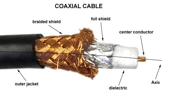
The first type of copper cable I’ll discuss is most likely a cable you’re familiar with. If you have a cable modem, then you’ve most likely seen a “coaxial cable.” Starting from the center of the cable itself, the “coax” cable possesses a long, central conductor wire. Hugging this central conductor wire is a di-electric or insulating material (Depending on the RG rating [discussed next], there may or may not be a foil shield.) The insulation, in turn, is surrounded by a braided, metal shield. The purpose for this braided shield is to prevent electromagnetic interference (EMI). Any devices in your environment that give off EMI, perhaps a television, fluorescent lighting, microwave ovens, and so forth, won’t affect the coax cable. The last layer of the coax cable is an outer black jacket.
Coaxial Cable Ratings (RG)
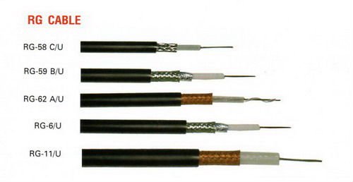
Your cable modems are usually connected via an RG-6 coaxial cable. The other type of coaxial cable you might see is an RG-59 coaxial cable. There are many other types of RG cabling, but RG-6 and RG-59 are the main two you’ll likely see. The “RG” stands for “Radio Grade” rating. Depending on which RG# you own, there will be a different “Ohm” rating. The Ohm rating is a relative measure of resistance, or rather, the ohm is the unit of measure for impedance, which is the property of a speaker that restricts the flow of electrical current through it. RG-6 and RG-59 coaxial cables both have an Ohm rating of 75, which will likely be printed on the cable itself. As you can see from the image below, RG coaxial cables all differ in size too. An RG-6 coaxial cable has a thick conductor wire whereas the RG-59 coaxial cable has a thinner conductor wire.
The connector type at the end of a coaxial cable varies. So, we’ll discuss a few of them here. Let’s start with the most common type of coaxial cable connector.
F-Connector
The F-Connector is most likely the connector type you’ve seen. If you’re using a cable modem, then the coax cable is probably giving you both cable and Internet access. The coax cable will come out of your wall, which will most likely be split with a coaxial splitter to make two coax cable connections. One connection will go to your cable modem and the other to your cable box. This implementation most likely uses the F-connector, which is threaded for easy screwing.
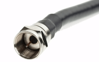
You can use your fingers or gently use pliers to twist the F-connector onto a connection. Be careful not to damage or bend the cable.
BNC Connectors
The last coaxial connector is the BNC connector, which isn’t exclusively for coaxial cabling. The BNC Connectors were used on older networks. These “bayonet-style” connectors could lock in place. BNC Connectors were created by Bayonet Neill-Concelman or Paul Neill (Bell Labs) and Carl Concelman (Amphenol). These days, you might see BNC connectors for T1 lines for a Wide Area Network (WAN).
For the BNC connector, just simply twist the connector and lock it in place. As we move on, I want to cover a piece of equipment that isn’t actually a coax connector type.
The Coaxial Splitter
I want to cover the coaxial splitter because it’s commonly used, especially in your home. The coax splitter does exactly what its name suggests, it splits the coax cable. These splitters are very useful for cable installations.

Check behind your television at home. You’ll probably find at least one of these laying around if you have a cable modem.
2. Twisted Pair Cabling
Now, we move on to the next type of copper cabling: Twisted Pair cabling. This is the most common type of cabling used on networks since the 1980s. It’s even used for our telephones. Basically, a twisted pair cable consists of 4 or more wires twisted around each other inside an outer jacket. The twisting of the wires prevents “cross talk” But, before we dive into twisted pair cabling, we need to divide it further, as there are two types of twisted pair cabling.
Shielded Twisted Pair (STP) cabling
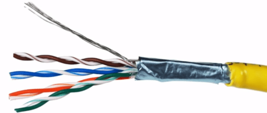
STP cabling still consists of wires twisted around each other; however, the bundle of wires are encased in a shielding to protect them from EMI. In the image below, there is a foil-based shield protecting the inner wires. STP cabling is only used in network environments where EMI is to be expected. For example, if a network tech needs to run a cable in an area where certain equipment might give off EMI (e.g., microwave ovens, fluorescent lighting, HVAC systems, etc.), then STP cabling wouldn’t be a bad idea.
If you’re going to use STP cabling, make sure it really is necessary because STP cabling is more expensive than our next type of twisted pair cabling.
Unshielded Twisted Pair (UTP) cabling
Our next twisted pair cabling it UTP cabling. Just like STP cabling, UTP cabling consists of wires twisted around each other, except there is no added shielding. UTP is the most common network cabling used by network technicians. Since UTP cabling doesn’t offer the same protection from EMI as STP or coaxial cabling, you should be careful about where you install UTP cabling.
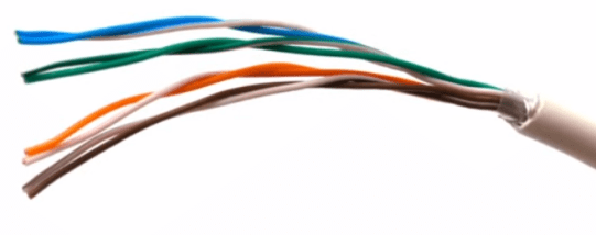
As you might have figured out, UTP cabling is less expensive than STP cabling, making it a flexible contender for use in our networks.
Twisted Pair Cabling Categories
All STP and UTP cabling comes in different flavors, and choosing which one fits your network needs might be difficult. Accordingly, the cabling industry has created different categories of twisted pair cabling. These “categories” are simply referred to as “CAT” ratings. Every CAT rating is rated by the highest frequency in Megahertz (MHz) the cable can handle. I’ve created a table to help distinguish between the many different CAT ratings.
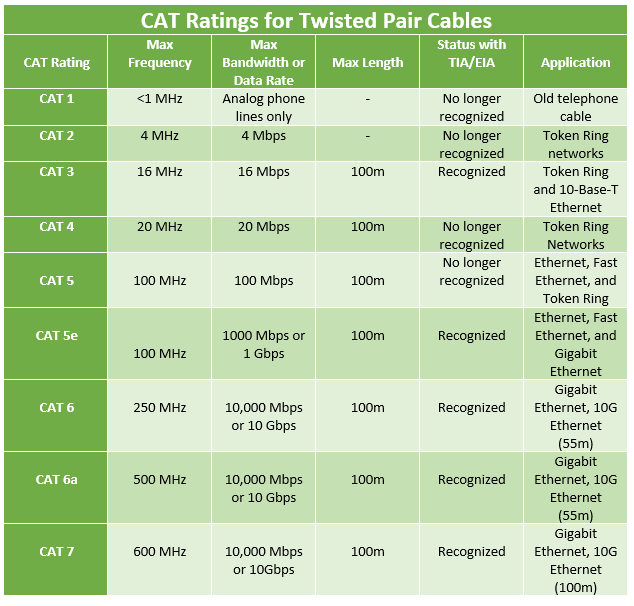
As you can see, each CAT rating comes with a maximum bandwidth rate, which is the maximum amount of data that travels through the cable in megabits per second (Mbps). All CAT ratings have the same length limitations (depending on the application), and based on its age, some CAT ratings are officially recognized by the EIA/TIA. The EIA is the Electronic Industries Alliance and the TIA is the Telecommunications Industry Association. There are other groups that also set the standards for cabling, such as ISO and ANSI.
If you review the table more in depth, you’ll notice that each CAT rating has its own application. What I mean by “application” is what is this CAT rating normally being used for? Since most networks today are employing 1000Mbps (or 1Gbps) Ethernet, you likely won’t be installing anything under CAT5e, although there’s an exception to older networks. If you’re installing cabling for a new network, you’ll most likely be installing CAT5e, CAT6, CAT6a, or possibly CAT7.
CAT5 was used on 100Mbps Ethernet, which was also called “Fast Ethernet (FA)” at that time (around the early 1990s). CAT5 was replaced by CAT5e, which was physically similar and supported the same max frequency rate, but CAT5e supported Gigabit Ethernet speeds, making it very popular in the beginning of the 21st century. CAT6 was the next step to better frequency and bandwidth, supporting up to 250MHz and 10Gbps. CAT6a runs at 500MHz and 10Gbps. Both CAT6 and CAT6a have additional sheaths protecting the cable from different forms of cross talk. In addition, the wires inside are also more tightly wound. However, if you’re going to use CAT6 cabling, make sure you understand the length limitations. Modern Ethernet standards state you can have 100m distances between the switch and the node, but this will vary if you are using CAT6 ratings.
The RJ-11 Connector
The “Registered Jack (RJ)” is the connector used for twisted pair cabling. Look closely at the image below. You’ll notice that the RJ-11 connector has 6 positions and 2 conductors, giving it the alternative name, a “6P2C” connector. This means 2 cables are terminating into this connector.
The RJ-11 connector was a very old connector type, and you’ll probably never see it unless it’s for an older telephone.
RJ-14 Connector
The RJ-14 connector uses 6 positions and 4 conductors, making it a 6P4C connector. This means 4 cables are terminating into this connector type.
Like the RJ-11, the RJ-14 connector is also used for phones.
RJ-45 Connector
The RJ-45 connector is the most commonly used connector type used for twisted pair cabling on modern Ethernet networks. It has 8 positions and 8 conductors (8P8C), meaning 8 wires in total are terminating into this connector.
The RJ-45 port is what you’ll commonly see on routers, switches, computers, and other devices.
Let’s now end our discussion on copper cabling and move on to the next broad type of cabling: Fiber-optic cabling
Fiber-Optic Cabling
Instead of using electricity to transmit and receive data across a wire, as is the case with copper cabling, Fiber-optic cabling uses light pulses (either LEDs or lasers). Since fiber-optic cabling uses light, there is no risk of EMI or wire tapping, making them a good option for government agencies and other companies/organizations to protect their data. An additional benefit to using fiber-optic cabling is the distance. Where modern copper Ethernet cables only travel 100m maximum, fiber-optic cabling can travel 10km (some can travel 40km!) without the signal degrading. If a network uses fiber-optic cabling, the cables are in pairs; one cable for transmitting and one cable for receiving. In some cases, the two cables are connected together for full-duplex.
The anatomy of a fiber-optic cable is pretty simple to understand. In the center is the glass fiber, or the “core.” Surrounding the core is a “glass cladding” which allows the light to reflect on and off as it travels down the fiber. There is also a buffer material to give the cable strength from bending and being stepped on. And finally, there is an outer jacket.
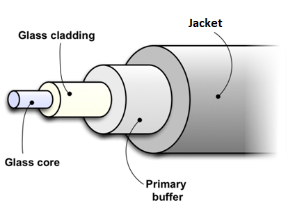
The size of the core cladding is going to vary from cable-to-cable, but generally, most are 62.5/125 microns.
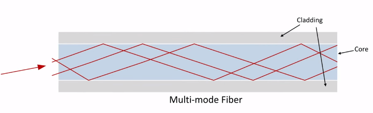
Multimode Fiber (MMF) Mode
If your fiber-optic cabling is using LEDs to transmit the light signals, then this is called “multimode fiber (MMF) mode.” LEDs aren’t as strong as lasers; therefore, light signals can only travel 2km as the acceptable distance range. That’s not bad. This would be good for data centers, servers, and connecting buildings together that aren’t too far away. MMF gets its name from how the light signals reflect off the cladding. As you can see below, the light is reflecting and bouncing off the cladding in many areas; thus, there are many”modes” for the light signals to take.
Single-Mode Fiber (SMF) mode
The “single-mode fiber (SMF) mode” uses lasers to transmit light signals instead of LEDs. With lasers, light signals can travel upwards of 100km, making it great for WANs and long distance connections. Unlike MMF mode, there are no multiple paths for the lights signals to take in SMF mode. As the image depicts below, the light signals are transmitting from one end to the other with very minimal bouncing and reflecting.

Verizon FiOS uses SMF mode fiber-optic cabling to distribute its services from a central Verizon FiOS office to your neighborhood, allowing the cabling to travel long distances to your home.
Fiber-Optic Wavelengths
Since we’re talking about light here, fiber-optic cabling uses different wavelengths of light, measured in nanometers (nm). If you’re using MMF mode, the MMF mode fiber-optic cabling will likely transmit in 850nm wavelengths. It doesn’t matter which standard you’re using; if you’re using LEDs, the wavelength doesn’t change. On the other hand, if you’re using SMF mode, you can see between 1310 and 1550nm wavelengths, depending on the power of the laser.
Now, we’re going to get into the different fiber-optic connector types. There are many different types of connectors for fiber-optics, but there are usually only four we give our attention to.
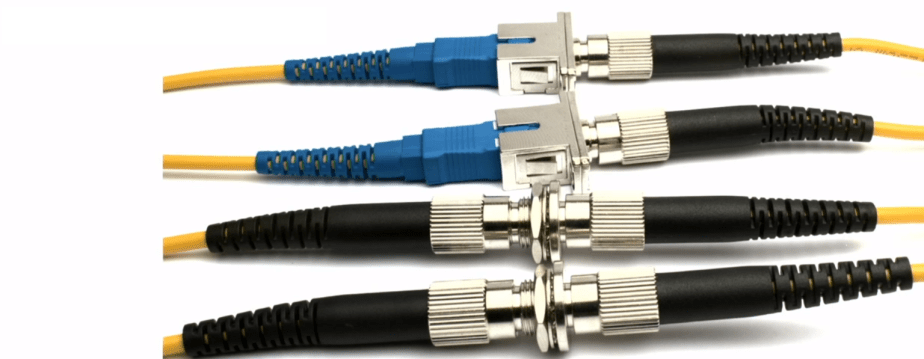
ST Connectors
ST connectors have been around for a long time. The “ST” stands for “Straight Tip.” It’s a bayonet connector (BNC) that locks in place and has a straight tip at the end, giving it its name. The problem with ST connectors is that twisting isn’t a delicate procedure to do when it comes to the very fragile fiber-optic cables. On top of that, if you had big hands, it was hard to twist on/off these connectors when they’re all closely packed.
SC Connectors
The SC connector goes by many names: Subscriber Connector, Standard Connector, and Square Connector. SC connectors were great, but network technicians complained about their relatively large size, which inhibited the amount of SC ports you could have on your devices.
FC Connector
The FC connector stands for “Field Assembly” connector or “Ferrule” Connector. This is great for environments that have a lot of vibrations because the FC connector is threaded. You simply put it in to the connector and twist it.
MT-RJ Connector
The MT-RJ connector is a type of “Small Form Factor (SFF) connector.” The “MT” stands for either “Mechanical Transfer Registered Jack” or “Media Termination – Recommended Jack.” As the purpose of an SSF connector, the MT-RJ connector was created to replace ST and SC fiber connectors. As you can see below, there are two fiber-optic cables terminating into the MT-RJ connector: one for transmitting and one for receiving for full duplex.
LC Connector
The LC Connector stands for “Lucent Connector,” “Local Connector,” or “Little Connector.” It is a type of Small Form Factor (SSF) connector also created to replace ST and SC fiber connectors. Just like the MT-RJ connector, it is full duplex. The LC connector has a lock that looks similar to the RJ-45 connector to lock the connection in place.
The single LC connectors may look like SC connectors; however, the LC connectors have the “lock” mechanism and the SC connectors don’t.
Fiber Couplers
If you need to connect different fiber-optic connectors together, then you can use what’s called a fiber coupler. Fiber couplers will connect different types of fiber connectors together no matter the difference. Just make sure you choose the correct fiber coupler to get the job done.
Notice how were connecting FC connectors with SC connectors and FC connectors with other FC connectors to extend the range of the fiber-optic cable.
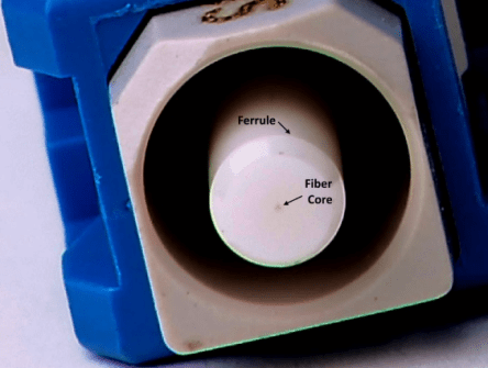
Connection Variations
Since we’re dealing with light, there is a possibility of “return loss.” Return loss is the amount of light that’s lost or reflected back to the source. Inside a fiber connector, you can see the fiber core. Surrounding the core is what we call the “ferrule.” This is a piece of hard ceramic designed to protect the fiber-optic as you insert and unplug your fiber-optic connections.
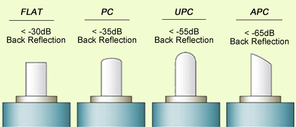
Besides the fiber-optic connectors we discussed, fiber-optic cabling differs vary in connection points (the tip of the ferrule). I’m not going to go into this topic today, but depending on the angle of the ferrule and how polished it is, you can minimize the amount of return loss.
Other Cables
1. Serial Cables
Besides copper cabling and fiber-optic cabling, there are other types of cabling that deserve to be mentioned, such as “Serial Cabling.” Serial cabling came before the PC was even invented back in 1980; therefore, when the PC was created back then, serial cabling was the only option. Serial cabling uses the “Recommended Standard (RS)-232.” The more common serial port found on older generation PCs were these DB-9s (meaning 9-pin).
There are many different variations of RS232 serial cables and ports. We often used to use these to connect to a modem, switch, firewall, or another device for a serial connection.
2. Parallel Connections
Parallel connections are about the same age as serial ports. They used a 25-pin, female DB-type connector. Parallel connections offer very slow data transfer speeds.

Conclusion
These are the many different categories and subcategories of cabling, as well as their various features. We’ve visited both old and new types of cabling. Hopefully, when remembering all of these different cables and their connector types gets confusing, you can reference this post. Or, you can invest in Mike Meyers’ N10-006 Study Guide or watch Professor Messer on YouTube. Pulling together all of you resources and putting them into a neat, and organized table also pays off a lot.
References
Hernandez, D. (2017). “Demystifying Ethernet Types— Difference between Cat5e, Cat 6, and Cat7.” Versa Technology, Inc. Retrieved from https://planetechusa.com/blog/ethernet-different-ethernet-categories-cat3-vs-cat5e-vs-cat6-vs-cat6a-vs-cat7-vs-cat8/
Meyers, M. (2015). All in One CompTIA Network+ Certification Exam N10-006. McGraw-Hill Education: New York, NY.
