
If you have trouble understanding this example, there will be a section at the end that will be less technological.
Introduction to the OSI model:
The best way to understand how computers communicate with each other is to first understand the OSI model. OSI stands for “Open System Interconnection,” and it provides us an easy reference model for how computers communicate with each other. It is a 7-layer model:

The way they taught us to remember it in school was to use mnemonics: “Please Do Not Throw Sausage Pizza Away,” or from top to bottom, “All People Seem To Need Data Processing.”
Let’s discuss how a computer accesses a Web page from a Web server. This example excludes DNS in order to keep it simple.
Layer 7 – Application:
The Application layer is everything you see on your monitor! It is the application or software you are currently using in front of you. For example, you use a Web browser application (e.g., Internet Explorer, Safari, Mozilla Firefox, and Google Chrome) to access a Web server. You type the address of a Web site in the URL bar and, using either http or https, you can contact the Web server hosting that specific Web site and request to view a Web page. These applications can include a number of additional functions, such as encryption, authentication, and tools that control how the data is displayed on your screen. Always remember, however, the Application layer does not refer to all applications, but rather network-aware applications.
Layer 6 – Presentation:
If you’ve ever seen the code language of a web page, you will know that it’s unreadable to the average Internet user. It’s all HTML, JavaScript, ASCII/Unicode, image files, and audio files…certainly not useful for us mere humans, but it’s useful to the Presentation layer.

The Presentation layer converts this machine-readable code into something we can easily read and “presents” it to us on our screen. It’ll pass this converted information up to the Application layer. In that way, you can actually see the images, hear the audio, and read the content on the Web page.
The Presentation Layer is always messy and difficult to understand in some examples. However, a cool feature of the Presentation Layer is that encryption and decryption occurs at this layer. If, for instance, you access a Web page via https, then TLS/SSL encryption/decryption occurs here.
Layer 5 – Session:
Before you can even see the Web page, you’ll need to create a “session” with the Web server. The Session layer connects applications to applications (e.g., your Web browser to the Web server’s application, such as Apache). This session is going to manage the communication between your computer and the Web server. Encryption is “initiated” at this layer.
The bottom line is that the Session layer creates sessions, manages them, accepts sessions, and opens and closes them. At any particular time, your computer can be managing hundreds and hundreds of sessions simultaneously.
Layer 4 – Transport:
The Transport layer is responsible for making a “TCP connection” to the Web server. TCP stands for “Transport Control Protocol.” This is a reliable form of transport since it creates a three-way handshake with the Web server, guarantees delivery of TCP segments, and requires error control. When your browser requests the Web page, the Web server will find the Web page you are requesting, and pass it to TCP. TCP will segment the Web page and package it into tiny blocks of data, called “segments.” Segments can also be called “packets.” If you’re using UDP, it’s called “datagrams.” They are the same thing. The information must be segmented based on the “Maximum Segment Size (MSS)” of the network. TCP will decide the size of each segment for the application data. Each TCP packet will then be encapsulated in what’s called a “TCP header.”
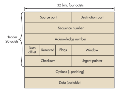
The TCP header contains both a source and destination port field. Ports are merely end-points for communication. The Web server is going to have a source port of either TCP port 80 for http or TCP port 443 for https. This is because protocols have their own specific ports assigned to them and protocols also have their own specific standards for transferring data. For example, File Transfer Protocol (FTP) uses TCP ports 20 and 21. Secure Shell (SSH) uses TCP port 22. All protocols have their own port number(s) assigned to them. The destination port; however, will be an available client-side port on your computer where you can receive the Web site information.
There is also a sequence number that uniquely identifies teach TCP segment. Underneath that is an acknowledgement number that indicates the sequence number that the segment creator expects to receive next. This is important for reassembling the TCP segments when they reach your computer.
You might be wondering why exactly this segmentation is even needed? I can explain this with a simple scenario. Imagine you are trying to download a 500MB movie file, but the maximum throughput on your network is only 54mbps. TCP can segment the 500 MB video file into 500, 1MB segments. This will fit into the MSS of the network.
Layer 3 – Network:
After TCP is finished with its job, it will pass the packets down to the Network layer, where IP will go to work. IP stands for “Internet Protocol.” IP uses IP addresses to identify the location where the information must be routed. IP encapsulates the packets with an “IP header” that looks like this:
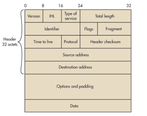
This is an IP version 4 header. The IP header contains many fields, but I’ll explain the more important fields. The IP header contains a version field, which will indicate if we are using IPv4 or IPv6. For simplicity, let’s assume we are using IPv4, which uses the older IP addresses (e.g., 192.10.0.1). There is also a protocol field that will specify the application protocol we are using. In this case, the application protocol will be http or https since we are requesting a Web page. There is also a source and destination IP address. The source IP address will be the Web server’s IP address and the destination IP address will be your IP address. This is because the Web server is sending information to you about the Web page you are requesting.
If it has to, IP will fragment the segments even further if its bigger than the Maximum Transmission Unit (MTU) size of the transmission media we are communicating over, such as Ethernet. These fragments are now called “IP packets.” Some people call them IP datagrams, but this is incorrect. When referring to a reliable transmission protocol like TCP, we call them “packets.” The identification field in the IP header will uniquely identify each IP packet. This will help your computer reassemble the Web site information when it reaches your computer.
Routers are layer 3 devices that will depend on these IP addresses. They need these addresses in order to know where exactly to route the information. So, IP is a necessity.
Layer 2 – Data Link:
The Data Link layer concerns itself with getting the data onto the wire, such as an Ethernet cable. If this is the case, then the IP packets will need to be formatted into Ethernet frames BEFORE it send the data to an Ethernet cable. This will happen once it hits the Web server’s Network Interface Card (NIC). NICs are simply computer hardware components that connect the device it is installed on onto a network.
The Data Link layer encapsulates the IP packets with an Ethernet frame header. An Ethernet Frame header looks like this:
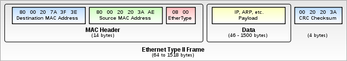
You’ll see that there is a source and destination MAC address field. MAC addresses are the physical addresses of NICs. The source MAC address will be the physical address of the Web server’s NIC and the destination address will most likely be the physical address of a switch that the Web server is connected to. Switches are called layer 2 devices and they depend on these MAC addresses.
Importantly, we can also have wireless NICs that format IP packets into 802.11 (wireless) frames. 802.11 frames are like Ethernet frames, except they are wireless and used for Wi-Fi. This will be important when the Web site information reaches your home router.
Layer 1 – Physical:
Once the Ethernet frames hit the Web server’s NIC and sent onto the wire, it is now in the realm of the physical layer. NICs are layer 1 devices.
Is that it? Not quite.
Now that the Ethernet frames have hit the wire, the Web information we have requested will traverse the Internet, hopping from router-to-router. These router hops will travel far and wide depending on your location from the Web server. It will travel through each network over the Internet until it reaches your default gateway. Since gateways must perform routing, you can also just call them routers. Your router knows the destination IP address thanks to the IP header created in the Network layer, and it will send it your requested Web site information to your computer via Wi-Fi. Note: Im skipping NAT and PAT here to keep it simple. If you were connected to a switch, then the router would send the Web site information to the switch, which would then forward the information to your MAC address. Thus, it’s back up the OSI layers from bottom-to-top.
Back to Layer 1 – Physical:
Most of us use Wi-Fi in our home networks. So, the Web information we requested will travel from our gateway/router via 802.11 (wireless) frames that contain the destination MAC address of your computer. Your router knows that you made a request to the Web server and it will send this Web information to the wireless NIC of your computer.
Back to Layer 2 – Data Link:
The Data Link layer is going to concern itself with getting the data we requested off the wire or off the wireless medium. It will therefore cast away the 802.11 frame header and sends the IP packets up to the Network layer.
Back to Layer 3 – Network:
IP is going to use the identification fields to reassemble the packets into their correct order, which creates TCP segments again. IP will check to make sure everything looks great at the Network layer. If it does, it sends the information up to the Transport layer.
Back to Layer 4 – Transport:
TCP is going to use the sequence fields to reassemble the TCP segments into correct order and in machine readable format. TCP will check to see if everything looks okay. If it all checks out and no errors are observed, it will send the information up to the Session layer.
Back to Layer 5 – Session:
The Session layer is still doing what it’s supposed to be doing, which is maintaining our session with the Web server. If you were using https encryption, then the Session layer will help decrypt it before sending it up to the Presentation layer.
Back to Layer 6 – Presentation:
The presentation layer converts the HTML, Javascript, ASCII/unicode, and image files to a format that our Web browser application can further process and display. In other words, it converts it to the correct syntax for our Web browser application.
Back to Layer 7 – Application:
Our Web browser application converts the syntax into human-readable format. Now we can enjoy the Web page we requested.
Still Don’t Understand?
If you have trouble understanding how this all works, I’ll explain it in layman’s terms. If you want to access a Web site, your Web browser must request a session with the Web server hosting that Web site. We use a special kind of protocol, called TCP, to establish this session. We love it because it’s really reliable. TCP segments the Web page information you are requesting into many, many smaller segments. Why? Because it’s easier to transfer that way. Each segment has a number that identifies it so it can later be put back together in the correct sequence.
The Web server and your computer both have an IP address. The Web server sends the information you requested to your IP address. Your home router will receive the Web site information and send it to your computer. Your computer will put all the TCP segments back together. The information is all machine language when it’s finally reassembled. But, the Presentation and Application layer are responsible for displaying all the data into a format that you can read on your screen.
Conclusion:
That’s it. As you can see, computers communicate in “layers” and we have the OSI model to help us better understand how this works. The really cool thing about this is that it all happens in milliseconds.

[…] to help us visualize what happens during node-to-node communication. I once made a post on the OSI model before, but it was lacking detail. There is another conceptual model that we use, called the TCP/IP […]
LikeLiked by 1 person