
“Transmission Control Protocol (TCP)” is defined in RFC 793. Its purpose is to govern the way in which computers exchange data and describe how reliable connections are created between a sending machine and a receiving machine. TCP works together with “Internet Protocol (IP).” Together, the TCP/IP protocol suite make up the rules that define the Internet (It pretty much is the Internet). ARPANet adopted TCP/IP back in 1983. There were many earlier standards of TCP beforehand, which were used to develop the modern version of TCP.
TCP was developed to be the first reliable connection-oriented protocol for host-to-host communication on computer networks. At the time, we were seeing an increasing dependence in computer communication systems, seeing as they play a very important role in military, government, and civilian environments. TCP was therefore developed as a way to interconnect these computer communication systems using a standard of protocols. 
TCP resides in the Transport layer of the TCP/IP stack. As we can see from the figure above, TCP sits just above IP in the Network/Internet layer. This layered protocol architecture was something I covered in an earlier blog post, which you can read about here. I would highly suggest reading this before moving on.
How Does TCP Work?
The purpose of TCP is to provide a reliable virtual circuit between between pairs of processes. To do this, TCP provides basic data transfer, reliability, flow control, multiplexing, connections, and precedence/security.
Basic Data Transfer
TCP transfers continuous data streams in octets. An octet = 8 bits. Arguably, you could just call it a byte, but RFC 793 refers to it as octets. TCP splits and packages these octets into “segments” before it is transmitted through a computer network. A “Push” function makes sure TCP sends and delivers the data to the receiving system. This is the transport process of TCP.
Reliability
TCP is referred to as a reliable protocol because it corrects any errors that occur during the transmission of data. Inevitably, TCP segments are lost, duplicated, or arrive at the receiving system in an incorrect order. To correct these errors, every octet is assigned a “Sequence Number,” which helps TCP reassemble segments in their correct order at the receiving end. Reliability is also accomplished with a process called “Positive Acknowledgement with Retransmission.” This process requires that the receiving system negotiate with the sending system a fixed byte-sized (or octet-sized) length of data, called a “window.”
The purpose of this window is to establish acknowledgements of data. For example, let’s say Host A is sending segments of data to Host B. Host A will document each segment, measured in bytes. After Host A sends the predefined amount of data that was established in the window, Host B must send an acknowledgment back to Host A that it has received this data before Host A can continue to send anymore segments. Essentially, Host A has to wait for this acknowledgement from Host B that it received the segments and is waiting for the next sequential segment. At the same time, Host A also starts a timer and will retransmit the data if the timer expires before it receives an acknowledgement.
Using the same example illustrated above, if Host B detects that it’s missing a segment in the data stream, it will send an acknowledgement to Host B to acknowledge this event and request a retransmission of the missing segment. Host A will then receive this acknowledgement and then resend the missing segment. After that, Host B sends another acknowledgement that it received the missing segment. Although this is a very fine-tuned and specific process, it is where TCP gets its reliability.
Flow Control
I just described “flow control!” The flow control function of TCP is actually achieved through the “window” function I explained above. This window specifies an acceptable number of octets/bytes to be sent before the receiving system must send an acknowledgement. Communication can be improved by increasing the window-size.
Multiplexing
TCP includes a useful function called “multiplexing.” This is the process of combining multiple signals into one signal. In TCP, however, multiplexing allows multiple processes within a single host to use TCP simultaneously. For example, when you open multiple tabs on Amazon, you’re creating multiple TCP sessions with a web server. Each session has its own unique “socket.” A socket is two-way communication link established through port numbers. In this case, every process has its own unique source port, but an identical destination port to the Web server. The sending host and the web server on the other side treats each session as a separate session. This convenient process works alongside the Session layer of the OSI reference model.
Connections
TCP establishes reliable connections through the processes described above (e.g., sockets/port numbers, windows, flow control, and sequence numbers). Together, these functions create a reliable “connection.” These connections are first initiated with a handshake mechanism called a “TCP Three-Way handshake,” which I will explain later.
Security and Precedence
RFC 793 doesn’t give much detail about security and precedence, but it does indicate that “users of TCP may indicate the security and precedence of their communication.” This is accomplished by the Type of Service (ToS) field in the IP header and security option field to provide precedence and security for each TCP connection.
Mode of Operation
TCP was designed as a way to interconnect computers on networks large and small. The processes that run inside a computer are responsible for producing and sending messages to other processes. As stated earlier, these processes communicate through ports. In order to transmit data across the network, a process calls on its TCP module and passes buffers of data as arguments. TCP packages this data into “segments,” which is a type of Protocol Data Unit (PDU). Each segment is encapsulated with a TCP header. Inside the header are fields that ensure reliable and ordered transmission of data. The segment is then handed down to the next layer where it will be packaged in another header and possibly fragmented even further in order to ensure successful delivery. This process continues until it hits the communication medium.
From there, the data is sent to a gateway (router). The gateway receives each segment and decapsulates, or “unwraps” the headers in order to determine which network the data should be forwarded to next. And if necessary, the gateway will fragment the data even further if the Maximum Transmission Unit (MTU) is exceeded for that network. Each segment is then “wrapped” again and sent off to the correct route.
The TCP Header
The TCP header has a total of 12 fields, each with its own particular responsibility. This is the 20- to 60-byte header that encapsulates each segment. I’ll briefly describe each field.

- Source Port: This field identifies the sending port number of the application on the transmitting host.
- Destination Port: This field identifies the destination port number of the application on the receiving host.
- Sequence Number: Sequence numbers are added to each header in order to assemble the data back in the correct order on the receiving host. The Sequence Number field has an additional role. If the SYN flag is set to a 1, this means that it’s the “Initial Sequence Number (ISN).” This is something I will explain in more detail momentarily; however, it is the first sequence number in the first byte of data.
- Acknowledgement Number: If the ACK flag is set, then the value is the TCP segment sequence number that is expected next.
- Header Length (or Data Offset): This field specifies the size of the TCP header. The minimum size is 20 bytes and the maximum size is 60 bytes.
- Reserved: Always set to 0.
- Code Bits (or Flags): There are a lot to know about flags. All-in-all, there are a total of 9 TCP flags. Each are 1 bit, which is either a 0 or a 1. If it’s a 1, then that particular flag is set. If it’s a 0, then that flag is off.
- NS: Experimental
- CWR: Stands for “Congestion Window Reduced.” At times, communication can be improved by decreasing the window size. This flag is rarely seen, but it is used in conjunction with the ECE flag.
- ECE/ECN: Also rarely seen and its role depends on how the SYN flag is set. ECN stands for an “Explicit Congestion Notification” on the network. Hosts that receive an ECN respond with a CWR flag.
- URG: Indicates that the “Urgent” pointer field is significant. This tells how many bytes are urgent in the TCP segment.
- ACK: All segments after the ISN should have this field set. With the ACK flag set, it indicates that the Acknowledgment field is significant. This helps with reliable communication via positive acknowledgment with retransmission and correct order assembly.
- PSH: The “Push” flag informs the receiving host to send the data to the receiving application immediately.
- RST: Stands for “Reset.” The RST flag resets the current connection.
- SYN: Only the first segment sent from each end should have this flag set
- FIN: Stands for “Finish.” By sending a message with the FIN bit set to the other side of the connection, a connection termination request is sent. The other side should respond with an ACK, but this is not always true. Then, it should respond with its own FIN. The other side should also respond with an ACK.
- Window: This field specifies the size of the window in bytes (or octets) that the sender of the data is willing to accept.
- Checksum: This field uses a Cyclic Redundancy Check (CRC) to check for any errors in the header or data field.
- Urgent: If set by the URG flag, it indicates the offset from the current sequence number, in octets, where the segment of nonurgent data begins.
- Options: Consists of 0 to 32-bit words. If set to 0, there are no options.
- Data: The actual data that was handed down from the upper layers.
Establishing Connections
This short discussion is centered on the TCP Three-Way Handshake, which focuses on how a client establishes a session with a host using TCP. Before any form of reliable communication can take place at the transport layer, a connection must be established between the client and the host. To complete this connection, we can refer to the image below. For simplicity, assume that the client computer wishes to connect to the server.
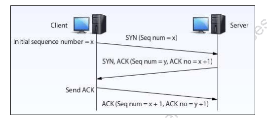
A simple and straight forward design of a TCP Three-Way Handshake between a client and a server. Reprinted from the online module “Enterprise Network Intrusion Prevention Systems,” by the University of Maryland University College, (2013). Retrieved from the University of Maryland University Web site. on
In order to initiate a TCP Three-Way Handshake, the client starts a Connection Request by sending a TCP packet with a synchronization (SYN) flag set and a random Initial Sequence Number (ISN), represented as the letter x. The ISN is a generated 32-bit number. Keep in mind that TCPs may have different mechanisms for picking the ISNs. The purpose of the ISN is to identify the first byte of data. They cycle every 4.55 hours in order to keep ISNs unique.
The second step of the TCP Three-Way Handshake occurs soon after the server receives the client’s SYN flag and ISN. This second step, also referred to as the “Connection Acknowledgement,” begins when the server delivers its own TCP packet. This TCP packet sent from the server contains its own unique ISN, represented as the letter y, as well as a SYN flag and an acknowledgement (ACK) flag. The ACK flag is supplemented with what is called an acknowledgement number (ACK No.). The ACK No. is the client’s original ISN with an added “1.” This is represented in the image above as x + 1. By adding a 1 to the client’s original ISN, the server acknowledges the client’s request for connection. This is how the client and server “initialize” on each other’s ISNs.
The final step in the TCP Three-Way Handshake is called “Data Transmission.” During this step, the client receives the server’s SYN+ACK flag and the ACK No. (x + 1) and then acknowledges the server’s acknowledgement of the connection request by essentially following the same process as the server did in step two. This third and final step is complete when the client sends an ACK flag to the server, along with a new ACK No., which is represented by y + 1. This new ACK No. adds a “1” to the ISN of the server’s packet. Once the server receives this data from the client, the connection is established between the two devices.
The process of selecting initial sequence numbers can be simplified in the figure below. Having unique ISNs and sequence numbers is what keeps connections separate and prevents unwanted duplications of segments. It also assists in preventing TCP Sequence Prediction Attacks, whereby attackers predict the sequence numbers in the TCP connection. Steps 2 and 3 in the figure below can actually combined. This is why we call it a “TCP Three-Way Handshake.”

A simple representation of the steps in a TCP Three-Way Handshake connection. Reprinted from “The TCP Split Handshake: Practical Effects on Modern Network Equipment,” by Beardsley, T., & Qian, J, 2010, MacroThink Institute, (2) 1, p. 199.
Besides the TCP Three-Way Handshake, there are other ways to establish a TCP session between two devices, such as the TCP Simultaneous Open method; however, I will neglect to discuss this method because although it is perfectly acceptable, it is rarely ever seen. So, just keep that in mind. It is also important to remember that each method of connection has its own risks and benefits.
There are different “states” of a connection as well during the connection setup. These states include: LISTEN, SYN-SENT, SYN-RECEIVED, ESTABLISHED, FIN-WAIT-1, FIN-WAIT-2, CLOSE-WAIT, CLOSING, LAST-ACK, TIME-WAIT, and CLOSED. They are pretty self-explanatory.
Conclusion
This discussion certainly should not be treated as an “all-there-is-to-know” about TCP. If you’re searching for a more extensively detailed “manual” on the functions of TCP, I would highly suggest reading RFC 793. This publication comes straight from the engineers who created TCP. Nevertheless, this discussion should be a sufficient reference to learners with an above-average understanding of networking concepts.
References
Beardsley, T. & Qian, J. (2010). The TCP Split Handshake: Practical Effects on Modern Network Equipment. MacroThink Institute (2) 1. Retrieved from http://web.archive.org/web/20130819045823/http:/nmap.org/misc/split-handshake.pdf
Goodrich, M. T., & Tamassia, R. (2011) Introduction to Computer Security. Boston, MA: Pearson Education, Inc.
Lammle, T. (2016). CCNA: Routing and Switching. Complete Study Guide. John Wiley & Sons: Indianapolis, IN.
Information Sciences Institute. (1981). Transmission Control Protocol: DARPA INTERNET PROGRAM PROTOCOL. Retrieved from https://tools.ietf.org/html/rfc793
University of Maryland University College (2013). Enterprise Network Intrusion Prevention Systems [Online Module]. Retrieved from the University of Maryland University Web site: https://leoprdws.umuc.edu/CSEC630/1306/csec630_01/assets/csec630_01.pdf

Your post of was realy informative
https://templeofelectronics.wordpress.com/2019/04/11/understanding-the-tcp-communication-3-way-handshaking-with-wireshark/
LikeLike