A “switch” is a Data Link (layer 2) device responsible for receiving, processing, and forwarding network traffic based on destination MAC addresses. Modern day switches are “smart” and manageable, either from a web console or a command-line interface (CLI). Due to the fact that they break apart collision domains, eliminate collisions, provide full-duplex communication, and provide many other benefits to our networks, switches have appropriately replaced hubs.
Switches Have Replaced Hubs
A “hub” is a layer 1 device that provides connectivity to devices, and nothing more. They were often used as a central connection point on the older star topologies, but network designers typically opt out for a switch instead due to its numerous advantages.
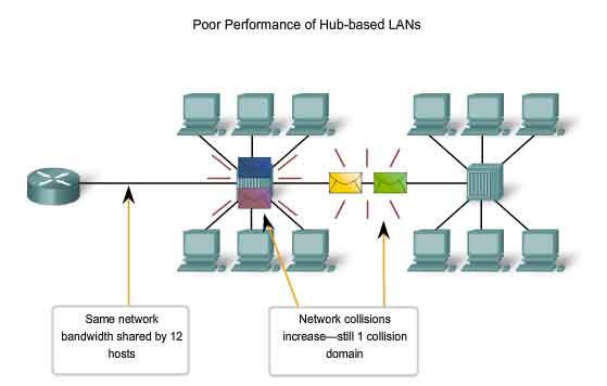
Hub-based LANs led to poor performance because every device connected to the hub was in one giant collision domain (and each switch interface is one separate collision domain). This also meant every device connected to the hub had to share the bandwidth among the other hub-connected devices. And, unlike switches, hubs could not “learn” the MAC addresses of the devices connected to its interfaces because it did not have a MAC address table to intelligently forward traffic or store hardware addresses.
Instead, if a hub were to receive data frames from a connected device on one interface, the hub would create a copy of the traffic and forward it out to all of its interfaces to the other connected devices. Only the device that the message was intended to will process the data; however, this does not change the fact that every device received a copy of that data. This takes up a lot of precious bandwidth, putting serious drag the network.
In addition, the fact that every node sees other node’s traffic poses an inherent security risk. Seeing as hubs provide no port security, it takes little effort for an unauthorized individual to plug a laptop into one of the hub interfaces and use sniffing software to eavesdrop on network communication. Hubs have no MAC address filtering or violation mode, which kind of makes them suck.
Switches Eliminate Collisions and CSMA/CD
While staying on the topic of hubs for just another moment, hubs also don’t prevent collisions. When two devices on a hub transmit a frame simultaneously, a collision occurs. This isn’t inherently bad on half-duplex Ethernet networks, but too many of them will downgrade network performance. Ethernet networks must therefore rely on a protocol called “Carrier Sense Multiple Access with Collision Detection (CSMA/CD)” in order to prevent collisions.
In CSMA/CD, a node senses if the wire is busy. If another node happens to be transmitting at that moment, the node will wait a few milliseconds and rechecks the wire. If the wire is free, the node can send out its frame. The wire is essentially first-come-first-serve, meaning all nodes have equal access to transmit on the wire as long as they sense it is free; hence the name “Carrier Sense Multiple Access (CSMA).” However, if a collision does occur, the hub sends out a signal that notifies the NICs. This is where the role of “Collision Detection (CD)” steps in. When a collision is detected on the wire, all nodes stop transmitting and random “backoff” algorithms determine how long each node must wait in milliseconds before they can retransmit again. The node with the lowest random number will get to transmit first, but once the timers run out, all nodes have equal priority to retransmit.
In the preceding situation, we see that half-duplex Ethernet networks cause undesirable congestion. This is because in half-duplex communication, the cable uses only one wire pair with a digital signal running in both directions on the wire. Both are responsible for transmitting and receiving, which is why we end up with collisions.
But, switches do not run in half-duplex, they run in full-duplex. Because switch ports run in full-duplex, we eliminate collisions and the need for CSMA/CD. This means every switch port is its own collision domain that provides its own independent bandwidth. Full-duplex communication uses two pairs of wires at the same time instead of a single wire pair. One pair of wires is used for transmitting and the other pair for receiving. This increases network transmission and eliminates collisions altogether since the wires are separated.
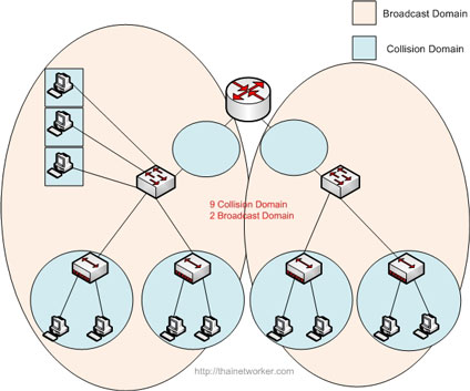
Each switch interface is its own collision domain while all hub interfaces are in an entire collision domain.
One thing to keep in mind is that although full-duplex communication is dominant nowadays, it’s still necessary to use half-duplex mode in some instances. If, for example, we have a host NIC only capable of half-duplex and it’s connected to a switch port capable of full-duplex, the switch must run in half-duplex mode and CSMA/CD applies.
How Switches Work: Address Learning and Forward Decisions
A network switch use “Application-Specific Integrated Circuits (ASICs)” to build and maintain a “MAC address table.” This table also goes by other names, such as a “Content Addressable Memory (CAM)” table, “filter” table, or “forward” table. They are all the same thing.
When a switch first powers on and completes the Power-On Self-Test (POST), the MAC address table is empty. Looking at the figure below, the switch has 4 active interfaces (Fa0/1-4) connected to 4 different hosts, respectively (A-D). Running the show mac-address table command reveals that the MAC address table currently has no entries.
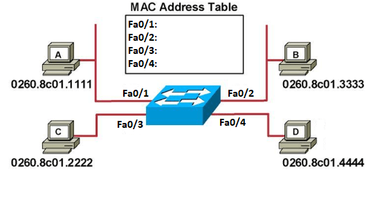
Once the hosts begin to communicate, the switch will start adding hardware addresses to the MAC address table. Say, for instance, host A sends a frame through interface Fa0/1 to host B. The switch will check the source and destination MAC address of the frame. Since host A’s MAC address is not in the MAC address table, the switch will add its hardware address to the corresponding interface in the MAC address table. And, since the destination address is also not in the MAC address table, the switch will flood all active interfaces with the frame, except for the port it came from (fa0/1). This process is called “unicast flooding,” and it will continue until the switch completes its MAC address table, as shown below.
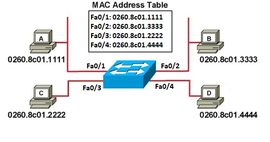
Unicast flooding temporarily treats these unicast (one-to-one) frames as broadcast frames, but it is necessary to build the MAC address table. Once, the table is complete, proper one-to-one communication can be established and the switch will forward frames only to their intended destinations via the correct switch port interface. The process looks something like this:

But, here lies an inherent security risk with switches. Unicast flooding ceases as soon as the switch adds each hardware address to its MAC address table, correct? But, when a switch runs out of room in its MAC address table cache, the switch begins unicast flooding once again. Attackers can flood a switch with spoofed ARP requests for the purpose of filling up the MAC address table. Once the MAC address table is filled with random MAC addresses, the switch is forced to flood legitimate traffic to flood every switch port because it no longer has the original entries. This allows the attacker to intercept traffic meant for other destinations. This is called a “Unicast Flooding attack” or “MAC Address Flooding attack.” This attack is used to obtain sensitive information and the MAC addresses of other connected nodes in order to perform MAC spoofing and MitM attacks.
Fortunately, this is easily preventable on Cisco Catalyst switches. For this type of attack to even occur, the attacker would need to plug his computer into one of the switch interfaces, which is probably unlikely considering that switches are usually locked in networking closets. Also, switch interfaces that are not active should be shut down to prevent unauthorized access.
Likewise, there are several switchport port-security commands that can assign MAC addresses to specific switch interfaces. This means that an attacker can’t simply unplug a node and replace the connection with his computer. Depending on which violation mode is set, the switch will either drop the attacker’s traffic, generate a log message, send an SNMP trap, and/or shutdown the interface entirely.
However, assigning MAC addresses to every single interface would be tedious. It would make much more sense to use the sticky command. This command assigns static MAC addresses to switch interfaces automatically. Take a look at the terminal below.
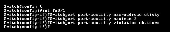
These commands, issued in global configuration mode for the Fa0/1 interface, assigns the first 2 MAC addresses coming into Fa0/1 as static MAC addresses. It also sets the violation mode to “shutdown,” which means if a 3rd unknown MAC address connects to that specific switch interface, that interface will shutdown, generate a log message, and trigger an SNMP trap.
Loop Avoidance
Switches are often connected together to provide connectivity and redundant links. This is good for availability, but it can also unintentionally cause “bridging loop.” When this occurs, broadcast storms can propagate on the internetwork and continually flood the network physical network media.

IEEE 802.1w, also called “Rapid Spanning Tree Protocol (RSTP),” effectively stops this from happening. It is the successor of the original IEEE 802.1d “Spanning Tree Protocol (STP).” With RSTP, convergence time is much faster. On an RSTP-enabled network, switches communicate with each other in order to block or forward specific ports in order to allow proper traffic flow. That way, if a switch does detect a change, it can act accordingly and avoid any loops. This can be accomplished using the spanning-tree portfast default command in global configuration mode on a Cisco Catalyst switch. This enables RSTP on all non-trunking ports, which means all access-ports.
In-Band Management of Switches
Smart switches can be managed through a web console or a command-line interface (CLI). If the switch comes with a web console, it must have an IP address. These types of switches usually come with a default IP address or it can be assigned dynamically via DHCP or statically via manually. While connected to the same LAN, all the administrator has to do is enter the IP address of the switch into a Web browser. This will bring up the switch’s web console interface.
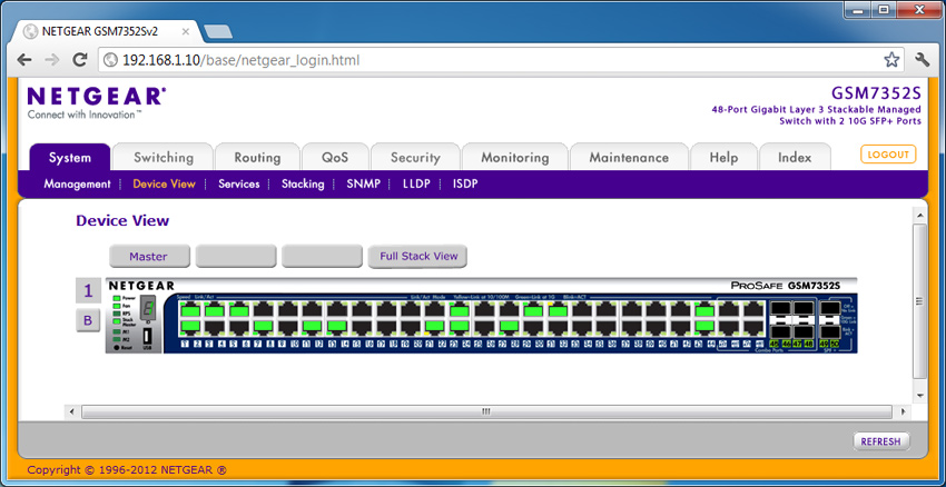
The switch’s web console shown above allows the administrator to make changes to the switch via an easy-to-use user-interface. From here, the administrator can change and enable/disable specific settings, such as port security, QoS, SNMP, VLANs, trunking, and so forth. The preceding example is a 48-port Netgear layer 3 switch with two 10-gigabit SFP+ ports. As a multilayer switch, it is contains virtual routing features.
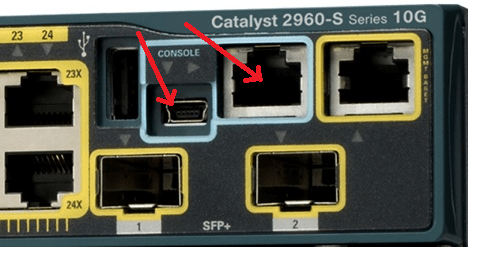
However, all Cisco switches don’t come with a web console; they come with a CLI. All Cisco switches come with every interface enabled and ready-to-go, but as a layer 2 device, they do not come with an IP address. So, if we want to manage the switch, we need to connect to the console port via a “console cable,” which is also called a “rollover” cable. It’s called a rollover cable because the pins on one side of the cable simply “roll” to the opposite layout on the other side of the cable. Many switches, like the Cisco Catalyst 2960-S now come with a mini-USB console port as well.
Rollover cables have a DB-9 serial connector on one end and an RJ-45 connector on the other end. We connect the DB-9 to the laptop and the RJ-45 to the console port…But wait, most modern computers aren’t going to have serial connections, they have USB ports. Therefore, we’ll likely have to use a “USB-to-Serial-Port adapter” to make the connection to the console port.
Once the connection is made, we can run a terminal emulator program, such as PuTTY to make a serial connection to the switch. Notice the settings of the PuTTY configuration.

These settings never change. Speed (baud) is 9600 bps, Data bits is 8, Stop bits is 1, Parity is none, and flow control is XDN,XDFF. From there, we will be able to connect to the console port.
Remote Management of Switches
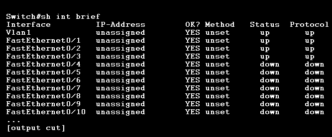
If we’re not physically present at your switch, you can assign a “management IP address” to our console port for remote management. Cisco switches do not come with a default IP address because switch interfaces are for layer 2; however, we can choose one of the VLANs on the switch to create a “Switched Virtual Interface (SVI).” Below shows the output for the show interface brief command:
Again, we can only configure a management IP address on the VLAN 1 interface because an IP address cannot be set on the FastEthernet layer 2 interfaces. To set a management IP address on the VLAN 1 interface, use the following command.
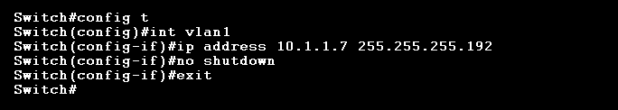
The IP address can be any host address we wish (but make sure the network address subnet mask is correct for your network). We also have to bring up the virtual interface with the no shutdown command. We should now be able to ping the switch. We can also verify the new configuration using the show interface brief command again.

With a management IP address, we don’t need a local connection to manage the switch. We can now use Telnet or SSH. Telnet, for example, is a virtual terminal emulator that will allow you to remotely manage a device without a console cable. Telnet can be used on a Cisco Catalyst switch using the telnet command. However, before we can use Telnet, the switch must have the “Virtual Terminal line (VTY)” password set on the switch using the line vty 0 command. Switches usually have 16 VTY lines.

We could technically bypass the Telnet password requirement by forcing the switch to allow Telnet connections without a password, but that’s not recommended. We should now be able to Telnet into the switch using the command telnet 10.1.1.7 from privileged EXEC mode. Keep in mind that if we Telnet into a switch, we need to also know the enable- secret to be able to get into privileged mode and make configuration changes.
Switch Port Security
We don’t want just anyone getting access to our switch. Cisco switches allow us to configure 5 different passwords, including console, auxiliary, telnet/SSH/VTY (which I just covered for Telnet), enable password, and enable secret.
The newer Cisco devices now use enable secret because it is preferably “encrypted” using a strong hash function. The enable password, however, is stored in plaintext unless it is used in conjunction with the service password-encryption command. We can see this if we use the show running-config command. You can use the enable secret to set a password for accessing various privilege levels on the switch.
If we want to set a console password, we can use the line console 0 command. This will make prompt all users with a login password if they want to access the console.
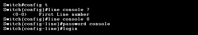
The line console ? command isn’t necessary, it’s just there to show that since we have only one console port, we can only choose line console 0. Applying the login command at the end means the switch will prompt an authentication for all console connections.
As I mentioned earlier, Cisco Catalyst switch interfaces can be protected with the switchport port-security commands. Before we can set any switchport port-security options on a switch interface, the interface must be set to an access port using the switchport mode access command. We can also see the switchport security options with the switchport port-security ? command.

These commands allow us to assign secure, static MAC addresses to an interface. This type of MAC address filtering prevents unauthorized individuals from connecting to the switch interfaces. There is also a violation mode that comes with several actions should a violation of switchport port-security occur. The default action is to shutdown the port, generate a log message, send an SNMP trap, and increment the security violation counter. But, there are also other actions to choose from, such as protect and restrict. Therefore, if we wanted to assign an interface a static mac address with a violation mode of restrict, it would look something like this:
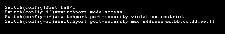
The restrict violation mode will drop all traffic from an unknown source MAC address until we remove enough secure MAC addresses to drop below the maximum value. But, just like shutdown mode, it also generates a log message, SNMP trap, and increments the security violation counter.
Conclusion
Switches are invariably very cool. There are so many topics to cover that it’s hard to touch them all. For example, switches aren’t always strictly layer 2 devices. Some switches happen to be both layer 2 and layer 3, like the Cisco Catalyst 3560 Series switches. These switches are also capable of something called “Inter-VLAN routing (IVR).” Speaking of “VLANs,” this is another powerful feature of switches that offers both better management and security to our networks. It’s a long topic, so I’ll have to cover it in another post. I did, however, cover a small introduction to VLANs here, but it’s only the fundamentals, and if you’d like a more serious discussion, I’d advise waiting for a future VLAN post.
References
Lammle, T. (2016). CCNA: Routing and Switching. Complete Study Guide. John Wiley & Sons: Indianapolis, IN.
Meyers, M. (2015). All in One CompTIA Network+ Certification Exam N10-006. McGraw-Hill Education: New York, NY.
University of Maryland University College. (2012). Switching and Routing Vulnerabilities. [Online Module]. Retrieved from the University of Maryland University Website

[…] connected to the WAP is in its own collision domain. Half-duplex wired Ethernet networks use “Carrier-Sense Multiple Access with Collision Detection (CSMA/CD)” to share the wire and detect frame collisions. But, since there is no way to detect […]
LikeLike