
Edit (7/18/2018) – This discussion focuses on Virtual Local Area Networks (VLANs). It is an introduction and a difficult concept to grasp for beginners. For intermediate-learners, I’d suggest reading this post instead.
Older Networks:
Our LANs can get messy. On our typically older corporate networks, there were many switches that separated different organizational units of a company into separate broadcast domains. In essence, switches were not only used for connecting devices and peripherals, but to also group computers together based on job function or department roles. For security reasons, this was a good thing because it restricted access to resources. For example, the Accounting & Finance department employees would be connected to a switch that had access to the Accounting server. However, the Marketing department employees, located in a separate broadcast domain, can’t access this server because, number one, they are on a different switch and, number two, access control restricts what they can access based on their privileges.
In the example just referenced, would it make sense for a Marketing employee to access the Accounting server? In my eyes, I see no reason for this. These two different departments may be able to contact other workstations in each department or share the resources in each department only if an administrator finds a reason to do so. If they are permitted, however, the Marketing employees would have to go up through a router, which would connect them to the destination LAN. Look at the diagram below to imagine what this might look like.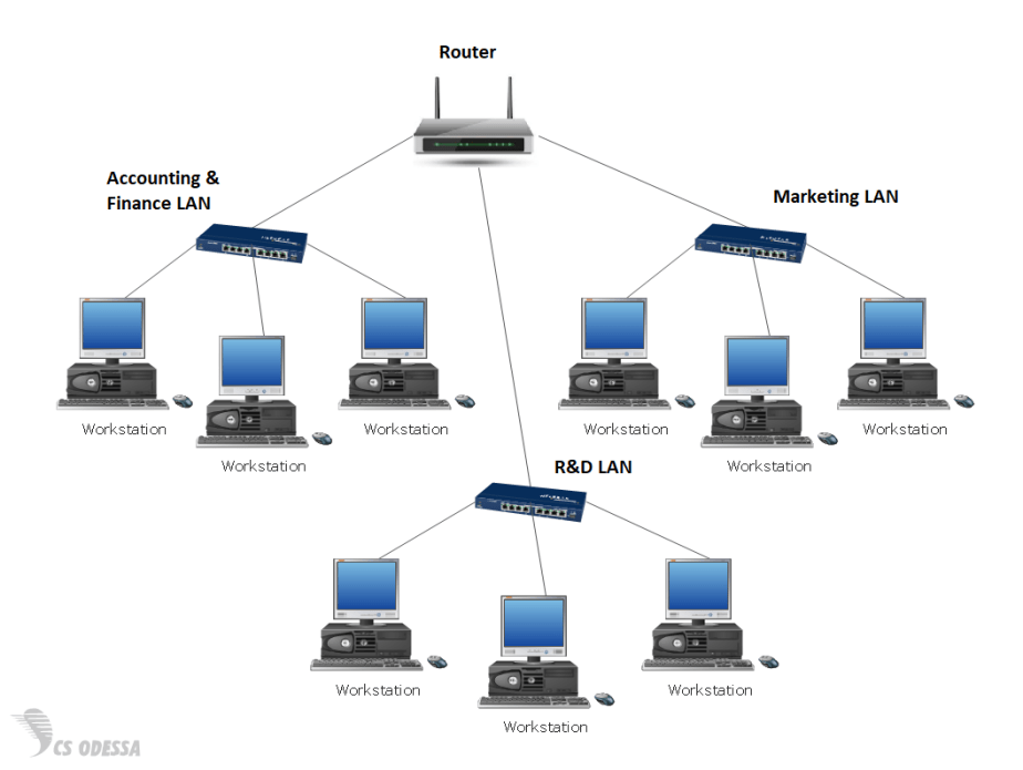
Enter VLANs
After examining the diagram above, you’ll see there are 3 separate LANs. Each department in our example company is assigned to one of these LANs on a switch.
- the Accounting & Finance LAN,
- the Research & Development (R&D) LAN, and
- the Marketing LAN,
The three LANs are all connected to their own separate switch. Each workstation in its LAN can access resources only in its local network. If a R&D workstation wants to share its resources with a workstation in the Marketing LAN, it will have to contact the router at the top. Depending on the security of the business, the router may forward or block this traffic for security reasons. This topology is fine for small networks, but as a company or business grows, this type of network becomes an administrative nightmare of too many switches, broadcast traffic, and increasing security risks. What will happen when new departments are added to the organization? More workstations? Everything will have to be updated and new switches and computers added to the network. Overall, it’s pretty inflexible and expensive, to say the least. However, what if you could logically segment the existing network with the switches you already own? Check it out:
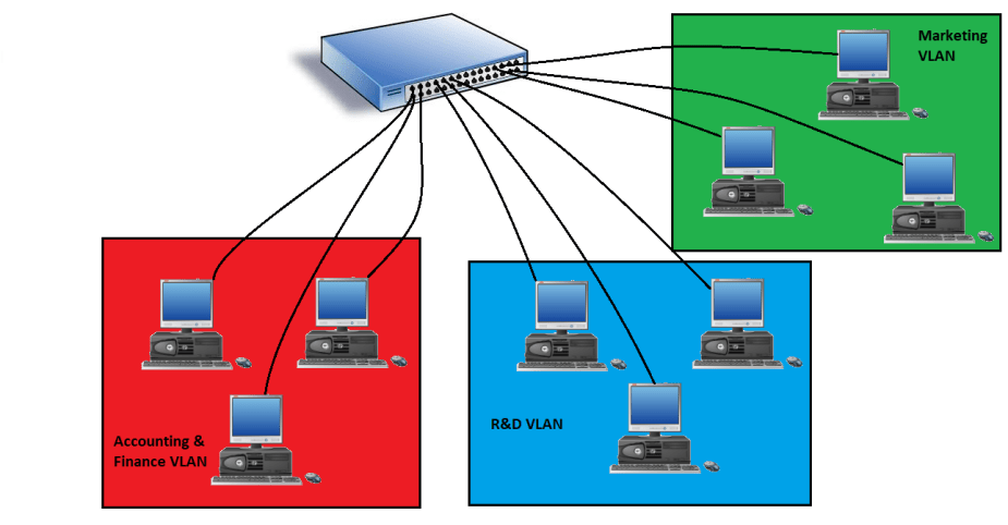
What we’ve done is take all three LANs and put them onto one switch! One switch now has multiple broadcast domains, which are called “Virtual LANs,” also called “VLANs.” All you have to do is assign the physical interfaces on a switch to a specific VLAN, a process called “VLAN Assignment.” VLANs are usually assigned a number, such as between 1 and 4094. The numbering scheme is up to you, but you cannot use VLAN 1 as it is the default VLAN. By default, all interfaces on a switch are assigned VLAN 1. In 802.q, this becomes the native VLAN (explained soon). After that, you simply put a workstation on a VLAN by connecting it the correct port. Voila! You now have VLANs.
But before, you can assign switch interfaces to VLANs, the interface must first be set to “access mode.” With VLAN management, VLAN assignments can be set up either manually by security and network administrators or automatically with Network Access Control (NAC) methods. Just like the first network topology example referenced at the beginning of this post, these VLANs are just like physical LANs. If the Accounting & Finance VLAN wanted to communicate with the R&D VLAN, it would still have to contact a router; however, if you trunk switches together, you can eliminate the router in between.
Trunking and 802.1Q
Serious and larger networks are obviously going to need more than one switch to support the multiple VLANs in their organization. We can connect multiple switches together using what’s called “trunking,” which is a type of link aggregation that connects switches together. Take a look below.

You can configure a physical port on each switch as a “trunk port” and connect the two switches together. If you have two switches that come from different manufacturers, don’t worry about any incompatibility issues as switch manufactures all follow the same standard for connecting switches together. That standard is called the IEEE 802.1q, or the “trunk standard.” Cisco has it’s own trunking protocol called “Inter-Link Switching (ISL),” but it’s moving more towards 802.1q.
To send information from a workstation on VLAN 100 to another workstation on VLAN100 on the same switch, the workstation sends an Ethernet frame to its access port on the switch. The switch checks for the destination address in its MAC address table. There is no tagging involved on the Ethernet frame because the destination is located on the switch and it’s been assigned to the same VLAN. The switch then sends it down the correct interface.
If, however, a workstation in VLAN100 on the Floor 1 switch wants to send information to a workstation to VLAN100 on the Floor 2 switch, an Ethernet frame must be “tagged” with a VLAN100 tag and sent to the Floor 2 switch. These are called “802.1Q VLAN tags.” If you’re using Cisco switches with ISL, it’s called an “ISL tag.” Ultimately, this is simply called “VLAN tagging” or “Frame tagging.” Don’t get mixed up in which term to use.
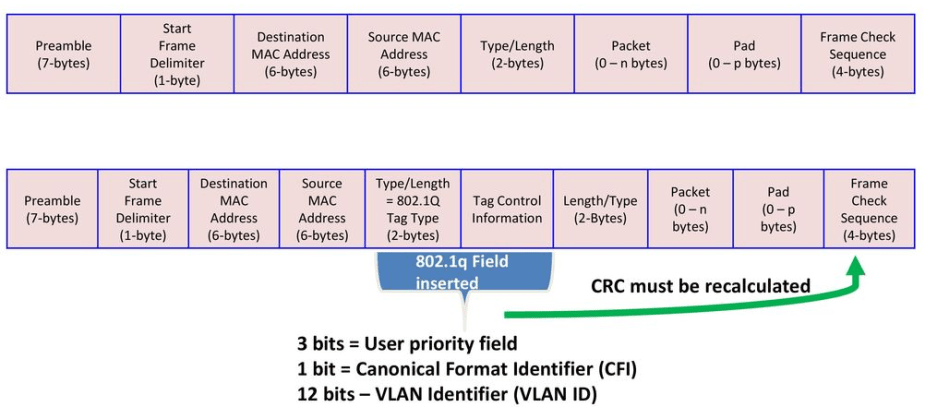
As we can see, an 802.1q field is inserted into the Ethernet frame to help identify the VLAN. The tagged frame is then sent down the trunk-link to the second switch with a new CRC. The switch then strips off the VLAN tag, checks the CRC, and sends it down the correct interface to the destination host on VLAN 100.
Trunking is great. We can connect VLANs 100, 200, and 300 on the Floor 1 switch together with VLAN 100, 200, and 300 on the Floor 2 switch. VLANs can now communicate across the building or in another building with ease. Trunking eliminates the need for a router in between the two switches. However, if for whatever reason permitted, a workstation on VLAN100 wanted to send information to a totally different VLAN somewhere else on the network, you’d have to either use a router or configure Inter-VLAN routing using a layer 3 switch.
InterVLAN Routing
You might be thinking that the concept of trunking switches together kind of sounds like routing, and you would be correct. Managed switches these days are capable of routing! I know, it’s weird after you’ve been told switches are layer 2 devices. When VLAN-capable switches connect together and send traffic to each other without the use of a physical router, it is called “InterVLAN routing.” To enable interVLAN routing between two VLANs on two different switches, you have to know the IP addresses and subnet masks of each VLAN. This makes the switch a layer 2 and layer 3 device. Now, different VLANs can communicate with each other, if permitted.
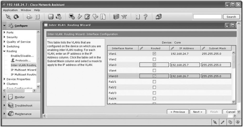
Cisco switches will normally not have a GUI like this unless you’re using some other form of software. It’s usually all CLI-based.
Easy Administration Using VTP
Obviously, managing all these VLANs still requires heavy administrative work. When your network grows, you’ll have to update the VLAN configurations manually. And once you update one VLAN, you may have to update the rest individually. But, if you are using Cisco switches, you can use Cisco’s proprietary protocol, called “VLAN Trunking Protocol (VTP).” Cisco really got it right here. VTP enables automatic configuration of VLANs. All you need to do is designate and configure one of your switches as a “server switch” and the rest of your switches as “client switches.” You do all of your VLAN configurations on the server switch and all of the client switches that connect to it will update their configurations automatically and accordingly.
Conclusion
These are the basics of VLANs. There are still more topics to cover regarding their security, which I intend to get into in another post. But, now we can truly appreciate virtualization as it really makes administration and management of out networks a lot easier and less expensive.
References
Meyers, M. (2015). All in One CompTIA Network+ Certification Exam N10-006. McGraw-Hill Education: New York, NY.

[…] limits the administrative work required for managing switches. If you’re unfamiliar with how VLANs work, you can check it out. If your workstation is connected to a switch, you usually only have […]
LikeLiked by 1 person
[…] so I’ll have to cover it in another post. I did, however, cover a small introduction to VLANs here, but it’s only the fundamentals, and if you’d like a more serious discussion, I’d […]
LikeLike