A “VLAN” is short for a “Virtual Local Area Network.” You can think of them just like an ordinary LAN where each LAN is its own subnet and broadcast domain; however, a VLAN is a virtual LAN. Take a look at the network design below. This is a 10.0.0.0/24 network, which gives us 1 subnet and a maximum of 254 available host addresses.
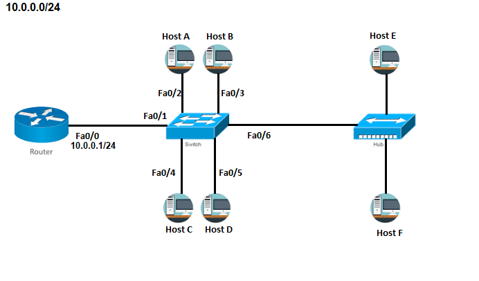
All hosts in the 10.0.0.0/24 network above have a default gateway on the Router’s fa0/0 interface at 10.0.0.1/24. Every host in this network is in the same broadcast domain, meaning Host A’s broadcast traffic will be “heard” by all other hosts in the subnet, whether they are connected to the switch or the hub.
But, let’s say I want to change this current network configuration so that Host A and B are on their own Sales subnet, Host C and D are on their own Marketing subnet, and host E and F are on their own Accounting subnet. To do this, I could subnet 10.0.0.0/24 further, physically put hosts on a different network, and change the default gateway address accordingly, but this would require I buy more network switches.
But, there is a better cost-friendly alternative that allows me to keep the same physical network design by logically separating the hosts into their proper subnets. This is where VLANs come in.
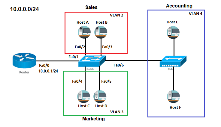
With this new VLAN design, Host A and Host B inside VLAN 2, Host C and Host D are in VLAN 3, and Host E and Host F are in VLAN4. Each VLAN is its own subnet and broadcast domain. This means that Host C, Host D, Host E, and Host F will no longer hear broadcast traffic from Host A and Host B. In addition, they cannot communicate with Host A or Host B unless I configure inter-VLAN routing. This is because no host can see the data traversing inside another VLAN other than the VLAN they are assigned. This means that Hosts in VLAN 2 can only see traffic meant for VLAN 2. Likewise, hosts in VLAN 3 can only see traffic meant for VLAN 3, and so forth and so on.
As we can see, adding VLANs increases the number of broadcast domains while simultaneously decreasing their size. This allows for better broadcast control, which in turn, improves network functionality because less broadcast traffic saves bandwidth and improves network performance since devices don’t have to process and respond to broadcasts. In addition, VLANs provide security by logically separating hosts on the same switch.
Configuring VLANs
To configure VLANs on a switch using the previous network design, use the vlan command in global configuration mode on a Cisco Catalyst switch. Use the ? for command syntax help.

Judging from the preceding output, there’s not much to choose from, which is good from a management perspective. I can choose between 1 and 4,094 VLAN ID numbers. If I want to assign VLAN 2 for Sales, VLAN 3 for Marketing, and VLAN 4 for Accounting, here is how I would do that starting from global configuration mode.
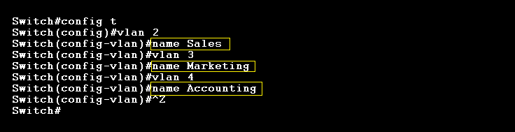
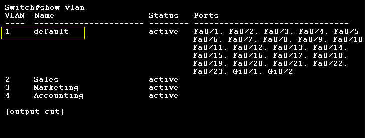
Each vlan is given its correct name using the name subcommand under vlan configuration mode. The terminal prompt changes to “(config-vlan)#” once we use the vlan command. Now, I can verify that my VLANs are created by using the show vlan command in privilege mode.
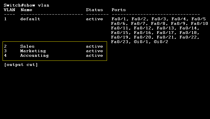
If you’re still in global configuration mode, you can use the do show vlan command. As we can see, the VLANs have been created and are active; however, there currently no interfaces assigned to any VLAN. By default, all interfaces are in VLAN 1, which is the “default VLAN.” I’ll talk a little more about the default VLAN and the native VLAN at the end.
Setting switch interfaces to a specific VLAN number is easy. By default, switch interfaces are set to “desirable” mode, but in order to add them to a specific VLAN, the switch interface must be changed to “access” mode. This is because access ports always belong to the VLAN they are assigned. Only devices connected to the same VLAN can send and receive traffic. Traffic that comes to that access port is automatically assumed to belong to the VLAN assigned to that port. In other words, it doesn’t actually know what VLAN it has been assigned, it just knows that traffic is originating from the same broadcast domain.

Notice how the interfaces were set to “access” mode. Now, we can verify that the switch interfaces are assigned their correct VLANs by using the show vlan command again.
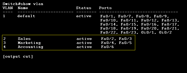
Perfect…
Configuring Trunk Links and IEEE 802.1q
A “trunk” link is a point-to-point connection that carries VLAN information using either Cisco’s ISL or IEEE 802.1q encapsulation. This connection can be between a switch and a switch, a switch and a router, or even a switch and a server. These are usually between 100Mbps to 10Gbps links, so you can use a FastEthernet or a GigabitEthernet interface.
We can create trunk links thanks to the IEEE 802.1q protocol. As an additional example, take a look at this new network design where I’ve trunked two switches together on a 10.0.0.0/26 network. There is VLAN 100 and VLAN 200.

VLAN 100 is configured to be in the 10.0.0.64/26 network, which means Host A, Host B, Host E, and Host F are all in the same subnet despite being on different switches. Thanks to that trunk link on Switch 1’s fa0/5 interface and Switch 2’s fa0/1 interface, Host A can communicate with Host E without going through the router. Likewise, Host C can also communicate with Host G without going through the router. This works through IEEE 802.1q’s frame-tagging process.
802.1q Frame-Tagging:
Here’s how this works using Host A as an example.
Host A creates a frame with Host E’s destination address and sends it up the switch fabric. Switch 1 checks for the destination MAC address in its MAC address table. If the MAC address were in the table, the switch would simply forward it down the correct interface; however, since Host E is on switch 2, this can’t happen. Instead, switch 1 “tags” the frame by inserting an 802.1q field.
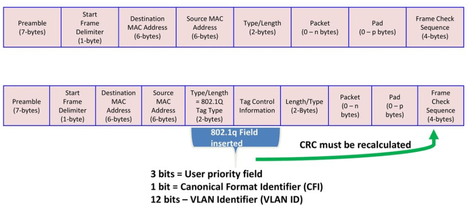
This field contains a VLAN Identification between 0 and 4094. Once the frame is appropriately tagged with the “VLAN 1 ID,” it forwards the frame out the trunk-link interface to switch 2. Upon receiving this frame, switch 2 determines the access port that matches the frame’s VLAN ID and destination MAC address. It then strips off the 802.1q field and recalculates the CRC in the Frame Check Sequence field and sends the frame to Host E down interface fa0/2.
Configuring Inter-VLAN Routing
By default, hosts located in different VLANs cannot communicate with each other. However, in many cases, hosts do actually need this connectivity and that’s where trunking and 802.1q encapsulation comes into play. One thing I can do is something called “Inter-VLAN Routing (IVR).” I’ll use the same network design from earlier, but add a few changes.
All I’ve done was change 10.0.0.0/24 to a /28. This would give me 16 subnets total with each one holding 14 hosts. I could’ve also chosen a 10.0.0.0/26 subnet as well, which gives me a total of 4 subnets and 62 hosts per subnet. But, if I want to create more VLANs later down the road, a /26 network won’t really do me any good. I’ve also made a few very easy configuration changes on the router and the switch.

Just like the original network design at the beginning of this post, you would similarly assign VLANs the same way. Take a look out the output below.
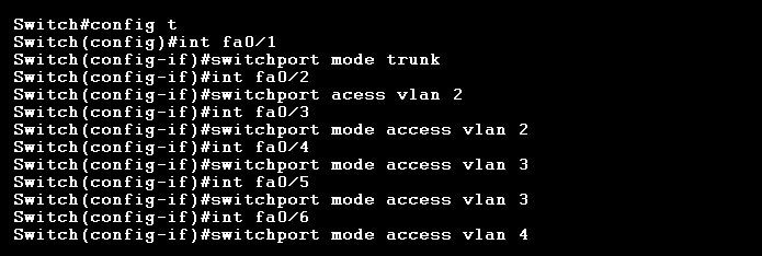
Except this time, notice that interface fa0/1 was set to “trunk” mode. I will explain why that is momentarily, but also notice how the remaining interfaces were appropriately set to “access” mode again.
The link between the router’s interface at Fa0/0 and the switch’s interface at fa0/1 is a trunk link. This particular trunk link is called a “Router-on-a-Stick (ROAS)” configuration. This allows all VLANs to communicate through one router interface. Logically speaking, here is how this looks. Notice how the link carries information from different VLANs.
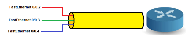
What I’ve done here is create something called “subinterfaces” on router interface fa0/0. Each subinterface address is the default gateway for the subnet/VLAN. Sub-interfaces are only “locally” significant, so it does not matter what number they are assigned. Since it doesn’t matter, it’s good practice to match the subinterface number with the VLAN number. This makes management a little simpler.
To configure the router’s fa0/0 interface to act as a ROAS, I must know the subnets for each VLAN. I can find the correct subnets by referencing the subnets that I added to the network design:
- VLAN 1 = 10.0.0.0/28 (default VLAN)
- VLAN 2 = 10.0.0.16/28
- VLAN 3 = 10.0.0.32/28
- VLAN 4 = 10.0.0.48/28
With this information, I can now configure the router’s fa0/0 interface in interface configuration mode. The encapsulation method we are choosing here is IEEE 802.1q, which is often referred to as “dot1q.”
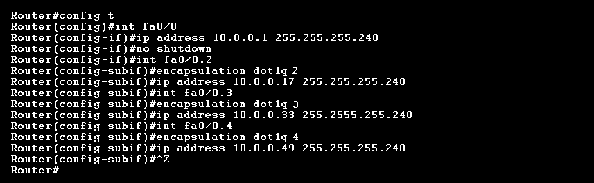
I did not have to configure VLAN 1 its own subinterface because, by default, all untagged frames are members of the native VLAN. Notice how each subinterface number matches the VLAN number that it’s been assigned. I assigned the default gateway address for each VLAN as the first host address available in that particular subnet. For example, the first host address in subnet 10.0.0.0/28 is 10.0.0.1.
Another thing I could do is use a Layer 3 switch, which is a type of multi-layer switch capable of both switching and routing at layer 2 and layer 3 such as the Cisco Catalyst 3560 switch. Below is a 192.168.10.0/24 and 192.168.20.0/24 network configured for both VLAN 10 and VLAN 20, respectively.
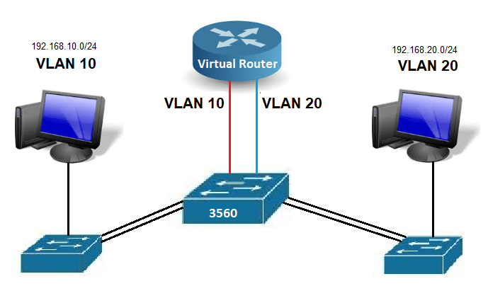
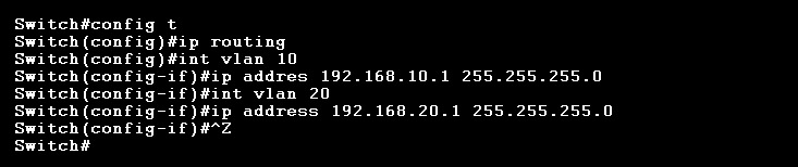
It looks like there is a router in this network design; in fact, it looks like a ROAS network configuration. However, there isn’t a physical router there. Assuming we’ve already configured the hosts in each VLAN with IP addresses, subnet masks, and the default gateway address, the only thing left to do is configure routing on the switch and create a logical interface for VLAN 10 and VLAN 20.
The Default and Native VLAN
I’ve been mentioning the default and native VLAN throughout this post and it’s important to know the difference between the two. Every interface on a Cisco switch belongs to VLAN 1 by default. This is known as the “Default VLAN.” As you saw earlier when I used the show vlan command, notice how each interface was originally configured on VLAN 1.
Unless the interface is acting as a trunk link, every switch interface will belong to VLAN 1 until you set the interface to access mode and assign it a different VLAN ID number. When you start a trunk link, the default VLAN now becomes the “native VLAN.” All data traversing the native VLAN is left “un-tagged.” The native VLAN is often reserved for legacy equipment, services, applications, or protocols that do not support 802.1q encapsulation, meaning they do not support frame-tagging. This is because some older services get screwed up if we manipulate the Ethernet frame by inserting an 802.1q field. Therefore, that type of equipment must stay in the native VLAN so that their traffic is left “un-tagged.”
Hackers often know that the native VLAN is usually VLAN 1, which means there could be vulnerabilities that can be exploited. For that reason, it’s good security practice to change the native VLAN number to something other than VLAN 1. If you do decide to change the native VLAN number, just make sure that both trunked switches have the same native VLAN number; otherwise, this will cause an error.
References
Lammle, T. (2016). CCNA: Routing and Switching. Complete Study Guide. John Wiley & Sons: Indianapolis, IN.
Meyers, M. (2015). All in One CompTIA Network+ Certification Exam N10-006. McGraw-Hill Education: New York, NY.
University of Maryland University College. (2012). Switching and Routing Vulnerabilities. [Online Module]. Retrieved from the University of Maryland University Website

[…] difficult concept to grasp for beginners. For intermediate-learners, I’d suggest reading this post […]
LikeLike